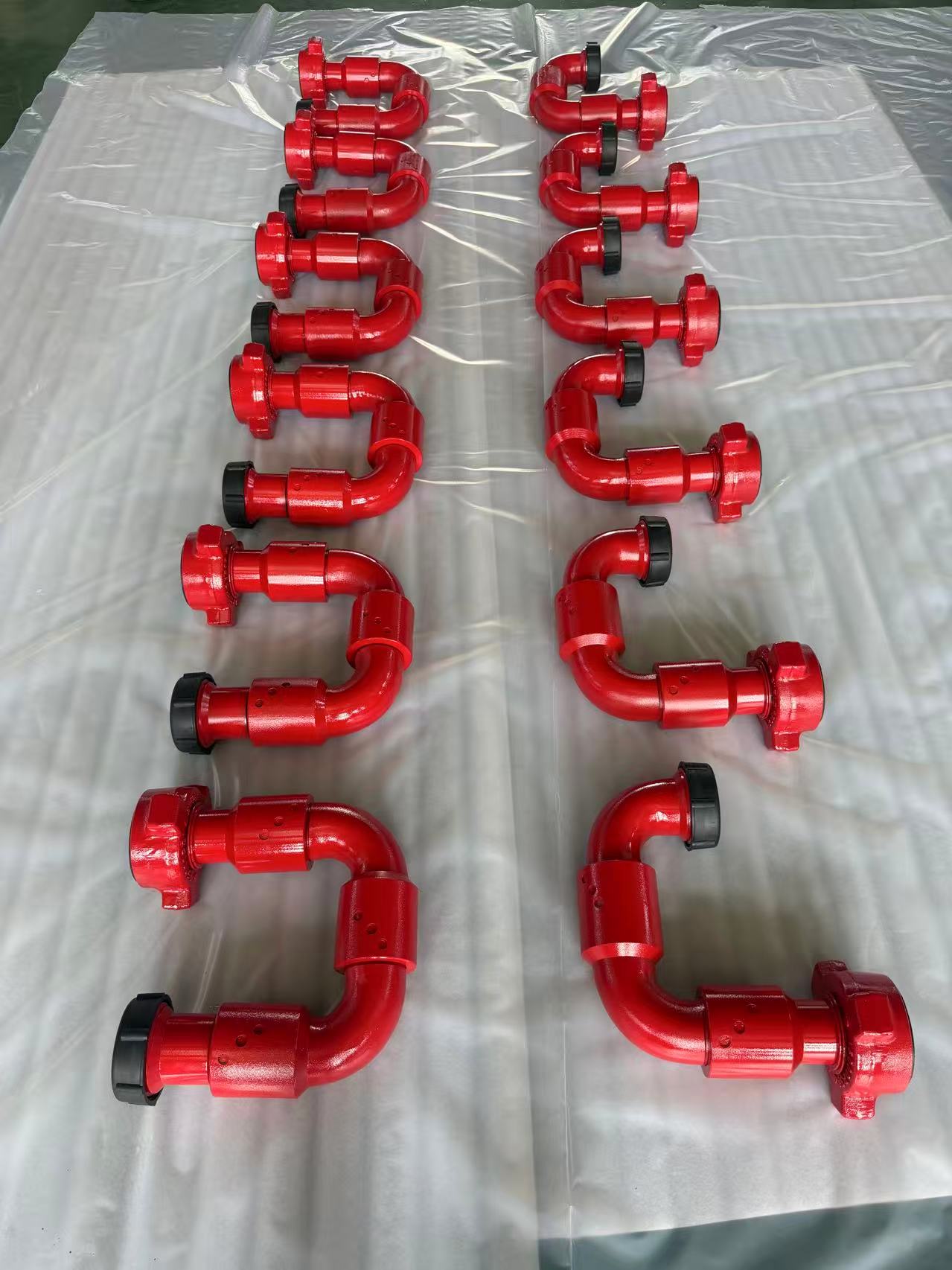
Treating iron is laid out in the order the fluid travels: from the pumps, through a manifold where individual pump lines join, along the main treating line, and into the wellhead. Each section is built from pup joints, plug valves, and swivel joints matched by size, union figure, and pressure rating, with the layout planned so every joint can be inspected, restrained, and reached safely.
Start with the flow path, not the pile of iron
A frac spread layout makes sense when you follow the fluid. Fluid leaves each pump through discharge piping, enters a manifold that combines the pump lines into a common header, and then travels through the main treating line to the wellhead and down the well. Treating iron is the high-pressure pipe, valves, and swivels that make up that path on the surface.
Planning the layout in that order keeps the build simple. Crews can see where pressure enters the system, where flow can be isolated, and where the line changes direction, instead of treating the spread as a random collection of joints that happened to fit.
The main sections of the layout
- Pump discharge lines: short runs from each pump to the manifold, built so a single pump can be isolated with a plug valve without shutting down the whole spread.
- The manifold: the junction where pump lines join the common header, with valves that let crews control which pumps are online and direct flow down the main line.
- The main treating line: the longer run from the manifold to the wellhead, made up of full joints and pup joints in 4 ft, 6 ft, and 10 ft lengths to close the measured distance.
- Direction changes and connections: swivel joints, including Style 10 and Style 50 arrangements, route the line around equipment and into the wellhead connection while accommodating the geometry of the location.
- The wellhead connection: the final section where the treating line ties into the wellhead, checked carefully because it is the last make-up before pressure reaches the well.
What gets checked as the line is built
Every component in the layout has to belong in the same pressure envelope. Crews confirm that size, union figure, and male and female orientation match at each make-up, and that the stamped working pressure of every joint, valve, and swivel meets the job plan. The lowest-rated component in the assembled line sets the limit for the whole line, no matter where it sits in the layout.
Fit matters as much as rating. Pup joints are chosen after the larger components are spotted, so the line closes without forcing unions together or crowding equipment. Swivels should align naturally with the route, without side loading, and the finished line should be supported and restrained under the site procedure, with unions accessible for inspection before the job and for safe break-out after it.
Why layout choices matter during the job
A clear layout pays off once pumping starts. Valves that can be reached safely make it easier to isolate a pump or section. A line routed with working clearance around it lets crews walk the iron, look for leaks or weeping unions, and keep people clear of pressurized sections. Spare pup joints and a spare valve staged near the line, rather than left on a truck, shorten any change the layout needs between wells or stages.
Layout is also a record-keeping habit. Noting which lengths and styles were used, and where, gives the next rig-up a known starting point instead of a fresh guess, and helps a buyer see exactly which pieces a complete package still needs.
Where Sterling can help
Sterling Wellhead stocks 2-inch FIG 1502, 10,000 PSI flow iron in Jourdanton, Texas 78026, including the T000856 plug valve, 4 ft, 6 ft, and 10 ft pup joints (T000864, T000866, T000855), and Style 10 and Style 50 swivel joints (T000620, T000693). If you are building out a treating line, send the lengths, styles, and quantities in your planned layout and our team will confirm the configuration by drawing number. Sterling is RFQ-only: contact sales@sterlingwellhead.com or +1 (512) 373-0384.
Frequently asked questions
What order is treating iron laid out in on a frac spread?+
In flow order: pump discharge lines first, then the manifold where those lines join, then the main treating line, and finally the wellhead connection. Building in that order makes isolation points and direction changes easier to plan and inspect.
Why are different pup joint lengths kept on a frac spread?+
Equipment rarely lands at a spacing that one standard length can close exactly. A mix of 4 ft, 6 ft, and 10 ft pup joints lets crews close the measured gap with proper union make-up and safe working clearance, and adjust when the layout changes.
What must match across every piece in the treating line?+
Nominal size, union figure, end orientation, and pressure rating must match the line the component is built into. Every piece must meet the job's pressure envelope, because the lowest-rated component determines the safe working limit of the assembled line.